


A measurement might indicate the sound level at the microphone's location, but it may not pinpoint the exact source of the signal.
Acoustic cameras are used to solve this problem. The system combines a microphone array, imaging cameras, and signal processing software to pinpoint the location of the sound source, then displays the results directly on an image of the test subject.
1. What is an acoustic camera?
An acoustic camera is a measurement system consisting of an array of multiple microphones combined with an optical camera. The signals received from the microphones are processed to determine the location and relative contribution of sound sources within the observation area.
The results are presented as a sound level map superimposed on a real image of the object. This allows engineers to simultaneously observe the product image and the location of the sound source on the surface.
This technology typically uses beamforming. Signals from multiple microphones are analyzed based on the differences in the time it takes for the sound to reach each microphone to determine the direction and relative position of the sound source.
The key to acoustic cameras lies not only in measuring sound levels, but also in their ability to help determine the source of the noise.
2. Operating principle
An acoustic camera system consists of three main components that work in sync:
- - Microphone array: Multiple microphones are arranged in a specific shape (circle, grid, star), capturing audio signals from multiple directions simultaneously.
- - Optical camera: Captures real images of objects to serve as a background for the overlaid sound map.
- - Beamforming software: Calculates the arrival time delay of sound at each microphone, thereby inferring the direction and intensity of the sound source, and then displays it as a color map (usually red - yellow - green in decreasing order of intensity).
The result is a visual sound distribution map, allowing engineers to precisely identify the location and area of noise generation on the product surface, rather than relying solely on the overall sound pressure level (dB) value.
3. Why are acoustic cameras useful in NVH testing?
Locate the noise source quickly and accurately.
Before acoustic cameras, engineers had to manually move individual microphones across different locations to locate noise sources – a time-consuming and error-prone process due to the need to repeat test conditions multiple times. Acoustic cameras shorten this process to a single measurement, displaying a complete map of noise sources in seconds.
Distinguishing multiple overlapping noise sources
In a running vehicle, there can be dozens of noise sources operating simultaneously—engine, tires, wind, HVAC system. Acoustic cameras help isolate and pinpoint each source within its own frequency range, allowing engineers to know exactly which source dominates the overall perceived noise level.
Supports faster design decision-making.
By accurately identifying the source of noise—for example, a small gap in the door seal or a resonance point on the vehicle's steel floor plate—the design team can intervene directly without the need for multiple detection tests, significantly reducing product development time and costs.
4. Application of acoustic cameras in cultural centers.
|
Application |
Measurement target |
Specific benefits |
|
Wind noise localization |
Identify the noise source at pillar A, mirror, and door seal. |
Precisely pinpoint the location of the air leak/vortex. |
|
Engine compartment noise analysis |
Identify which component (fan, gearbox, motor) is the noisiest. |
Prioritize addressing the source of the greatest impact. |
|
Check HVAC system noise levels. |
Locate the noise source in the ductwork or fan. |
Detect fan imbalance or air leaks. |
|
Interior noise test |
Identify the source of the creaking or rattling sounds. |
Reduce manual search time in the cabin. |
|
Testing of electronic products, electric motors, and electric vehicles. |
Locate the source of the howling sound from the inverter and electric motor. |
Analysis of high-frequency noise sources characteristic of electric vehicles. |
5. Technical factors to consider when choosing an acoustic camera.
- - Number and configuration of microphones in the array: Arrays with multiple microphones offer better spatial resolution, but this needs to be balanced with cost and intended use.
- - Operating frequency range: Must match the phenomenon being measured - engine noise at low frequencies requires a different array configuration than brake screeching at high frequencies.
- - Optimal measurement distance: Each type of microphone array has a specific effective measurement distance - measuring too close or too far will affect positioning accuracy.
- - Integration with existing DAQ systems: Ensures synchronization of acoustic camera data with other vibration and sound sensors in the same test.
6. Acoustic camera solutions from Head Acoustics
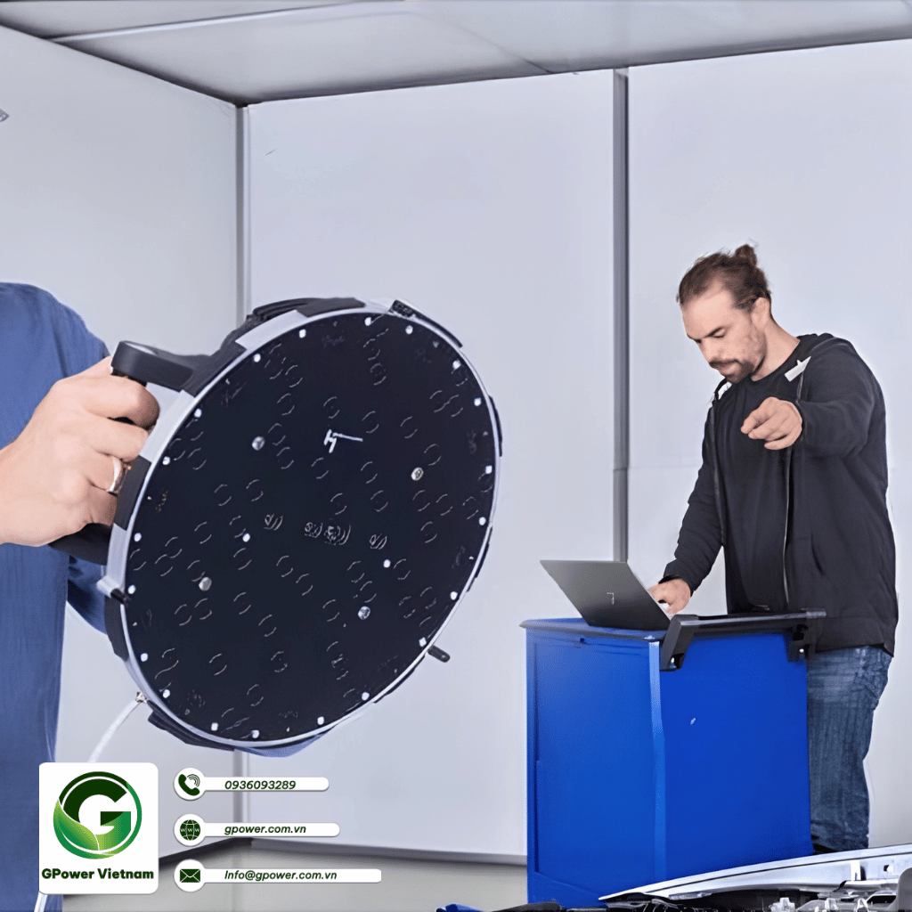
6.1. HEAD VISOR VMA V (New generation, most versatile handheld vibrator)
This is the company's leading modern portable acoustic camera model. A special feature of the HEAD VISOR VMA V is its ultra-lightweight, modular hardware structure that allows for easy disassembly and expansion:
- - Basic configuration: Uses a 30 cm diameter circular disc with 60 built-in microphones . This design is very compact, ideal for close-up measurements or in confined spaces such as car interiors.
- - Expandable configuration: When measuring low-frequency sound sources or at long distances, users can add 10 spiral arms to increase the array diameter to 1 meter , with a total of 120 microphones .
- - Key features: The device has a built-in 7-inch multi-touch screen for viewing results directly, a depth-sensing camera for accurate distance calculation, and AI algorithms to optimize spatial resolution.
6.2. HEAD VISOR flex (Highly customizable series for laboratories)
This device is designed for engineers who need a measurement system with absolute geometric customization.
- - Features: The entire microphone array size, the number of recording channels, and the geometric layout are all flexibly adjustable.
- - Application: This system is typically combined with the manufacturer's specialized HEADlab data acquisition hardware to support complex NVH testing in wind tunnels or large industrial production lines.
6.3. HEAD VISOR VMA III.0 (Large-sized specialized series)
For applications involving measuring sound sources at very long distances or testing large objects (such as airplanes, locomotives, or complete automobiles from the outside), this large array product line is a suitable choice.
Features: The system boasts a massive microphone array with a diameter of up to 3 meters , comprising 14 spiral arms containing 112 microphones , and is integrated with three cameras for wide-angle panoramic scanning.
GPower Vietnam – Acoustic camera solutions for NVH labs
Choosing the right acoustic camera system – from microphone array configuration to beamforming software – requires a thorough understanding of each customer's specific testing requirements. GPower Vietnam supports businesses throughout this entire process:
- - System selection consultation: Determine the acoustic camera configuration suitable for the frequency range and type of noise source to be located.
- - Supplier consultation: Connect with reputable acoustic camera brands within our international partnership network.
- - Integrated solution consulting: Ensuring the system operates seamlessly with the client's existing analytical software and DAQ system.
- - Calibration, warranty, and maintenance: Long-term technical support services ensure the acoustic camera system always operates stably and accurately.
Contact GPower Vietnam today for advice on the most suitable acoustic camera solution for your NVH lab - Hotline: 0936093289 | Email: info@gpower.com.vn


 Info@gpower.com.vn
